Pipe Marker Placement: Where They Go and How They Stay
Our ASME A13.1 guide covers what the marker looks like — color field, letter height, legend. This one covers the half that actually determines whether the system works: where each marker goes, how the spacing logic runs, which way the arrow points, and what to do on the pipes that fight back — sweating chilled lines, insulated steam, and valves too hot for any label.
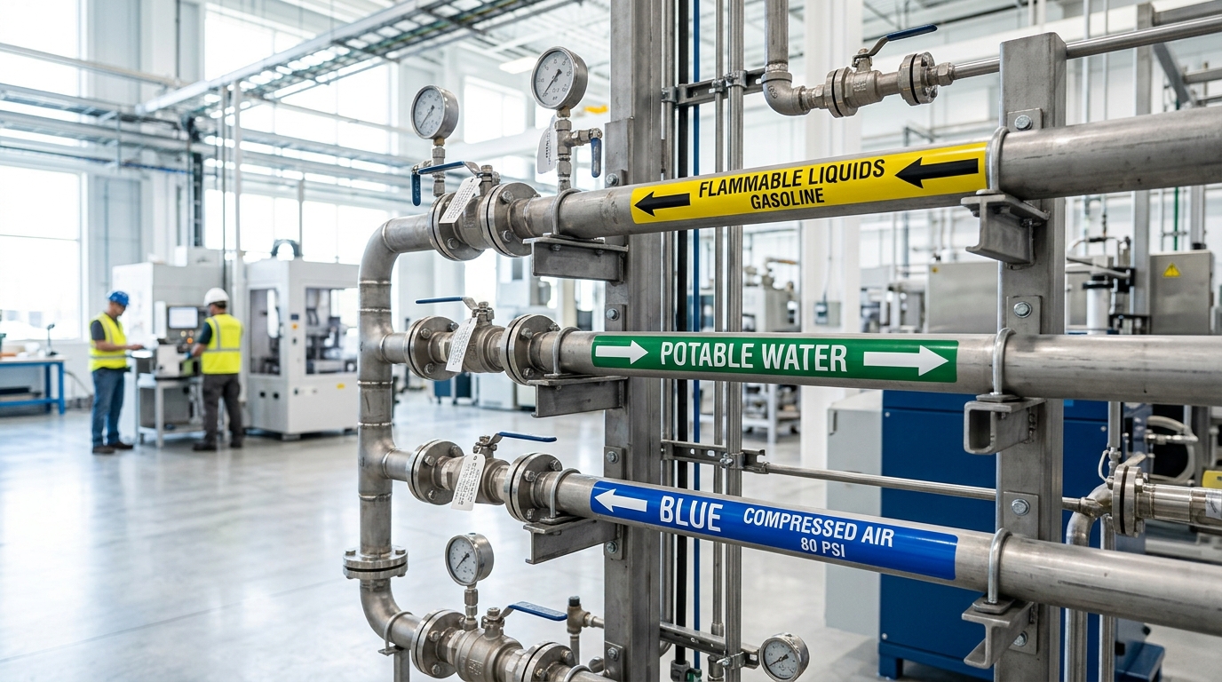
1. The Six Placement Locations
Walk any line from source to load and mark at these points; the straight-run interval fills the gaps between them:
2. Technique: Angle, Arrows, and the Hard Pipes
- Rotate the legend to the reader: below centerline for overhead runs, on it at eye level, above it for low runs. Verify from the actual walkway, not the ladder you installed from.
- Every marker carries a flow arrow; bidirectional lines get arrows both ways. An unlabeled direction is a half-labeled pipe.
- On insulated pipe, the marker adheres to the jacket — clean the jacket first, and size the marker to the outside diameter of the insulation, not the pipe. The OD determines letter height under A13.1.
- Sweating chilled lines get strap-on or snap-around carriers — mechanical grip, no adhesive to undermine. Same logic as the no-adhesive half of the catalog.
- Application basics from the adhesive guide apply: IPA wipe, firm full-width pressure, above minimum application temperature.
Material baseline: B-595 vinyl (-40°C to +82°C) printed on an i5300 or S3100 covers standard mechanical rooms end to end — the color code chart lives in the ASME A13.1 guide.
3. Valve Tags: Where Polymer Gives Up
The valve schedule is the facility's cross-reference: tag number on the valve, service and normal position in the log. On hot service, the tag material question answers itself:
The classic stamped valve tag — steam, condensate, hot water trim.
Corrosive and highest-heat service; survives wire-brushing and repainting cycles.
Ambient utility valves, paired with a printed wall-mounted valve schedule.
Need the color code and sizing tables?
The companion ASME A13.1 guide carries the full color chart, pipe OD sizing table, and letter height requirements this placement system assumes.