Electrical Standard for Industrial Machinery (Harness Wire Numbers & Operator Controls)
Applies to the electrical/electronic equipment, apparatus, and systems of industrial machines operating at 1000V or less (CNC machine tools, automated assembly lines, packaging robotics, and material handling systems). Mandates wire marking, grounding identification, and safety operator control labels.
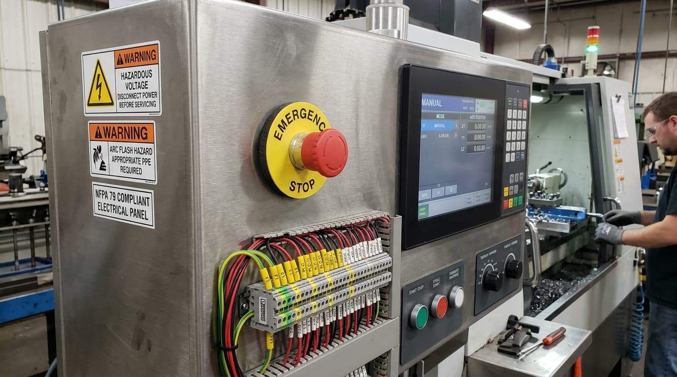
All conductors must be marked with identification corresponding to the technical documentation at each termination point. Markings must be oil-resistant, abrasion-resistant, and remain legible throughout the operational lifecycle of the machinery under continuous machine vibration and coolant mist.
NFPA 79 vs. NFPA 70 (NEC) Machinery Mandates
The National Electrical Code (NFPA 70) governs building electrical infrastructure and service entrance equipment. NFPA 79 applies specifically to the electrical and electronic equipment of industrial machines starting at the point of connection of the electrical supply to the machine disconnect.
NFPA 79 Pre-Audit Inspector Verification Checklist
Review these 5 critical inspection points before the Authority Having Jurisdiction (AHJ) or field auditor inspects the installation:
Section 13.2 Conductor Identification
Verify all internal and external control circuit conductors are identified at each termination point matching schematic wire numbers with heat shrink (B-342) or wrap labels (B-427).
Section 10.7 Emergency Stop Push-Button Plate
Ensure emergency stop palm buttons are mushroom type, colored red, and mounted on a yellow circular background legend plate reading EMERGENCY STOP (Brady B-593 yellow/black).
Section 5.3 Main Disconnect Labeling
Check that the main machine power disconnect is clearly marked with its operating voltage and labeled 'MAIN DISCONNECT' on the handle assembly.
Section 8.2 Grounding & PE Symbol Verification
Verify green/yellow PE terminal markers are installed at all protective bonding circuit terminations.
Section 16.5 Warning Signs for Hazardous Voltage
Confirm safety signs meeting ANSI Z535 are affixed where live parts operating at >50V are accessible (Brady B-595 vinyl).
NFPA 79 Certified Material Substrate Adhesion Matrix (ASTM D1000)
| Material Code | Stainless Steel (HSE) | Textured Powder Coat (28 dynes) | Cast Aluminum | Polypropylene (LSE) | Engineering Verdict |
|---|---|---|---|---|---|
| Brady B-593 | 95 oz/in | 90 oz/in | 90 oz/in | 75 oz/in | Yellow/black circular emergency stop push-button plates |
| Brady B-342 | Recovered | N/A | N/A | N/A | 3:1 flame retardant heat-shrink wire sleeves |
| Brady B-595 | 80 oz/in | 70 oz/in | 75 oz/in | 55 oz/in | Machine safety decals resisting coolant & cutting oil |
Key NFPA 79 Regulatory Clauses & Mandatory Specifications
| Clause / Section | Regulatory Requirement | Technical Compliance Mandate | Certified B-Numbers |
|---|---|---|---|
| Section 13.2 | Conductor Identification Rules | All power, control, and signal conductors must be uniquely identified at each termination point matching schematics. | |
| Section 10.7 | Emergency Stop Operator Marking | E-stop palm buttons must be red mounted on a yellow circular background legend plate reading EMERGENCY STOP. | |
| Section 5.3 | Machine Disconnect Identification | Main disconnect device handle must be clearly marked with voltage ratings and labeled 'MAIN DISCONNECT'. | |
| Section 16.5 | Hazardous Voltage Warning Decals | Warning signs meeting ANSI Z535 must be affixed to enclosures containing live parts operating at >50V. |
Certified Brady Materials & Mandated Ribbon Formulations
Brady Series R10000 Premium Outdoor Resin Ribbon
Brady Series R6600 Pure Resin Ribbon
Brady Series R6000HF Pure Resin Ribbon
Orderable Commercial SKUs & Distributor Part Numbers
Build & Size Your NFPA 79 Conductor Schedule
Import AutoCAD Electrical wire from/to reports, apply 10% scrap safety factors, and calculate exact roll quantities with 1 click.
NFPA 79 Frequently Asked Compliance Questions
What does NFPA 79 require for wire identification inside industrial machinery?
NFPA 79 Section 13.2 requires all power, control, and instrumentation conductors to be uniquely identified at each termination point (source and destination) matching the machine's electrical schematic diagram. Markers must be durable heat-shrink tubing (Brady B-342) or self-laminating vinyl wraps (Brady B-427) that cannot slip or fall off.
What is the NFPA 79 requirement for Emergency Stop push-buttons?
NFPA 79 Section 10.7 mandates that Emergency Stop actuators must be palm/mushroom-head type, colored red, and mounted against a yellow background. The yellow background must be a circular legend plate labeled 'EMERGENCY STOP' (Brady B-593 yellow/black legend plate).
What conductor insulation color codes are mandated by NFPA 79?
NFPA 79 Section 13.2.4 specifies: Black for ungrounded AC power conductors; Red for ungrounded AC control circuits; Blue for ungrounded DC control circuits; White or Natural Gray for grounded AC neutral conductors; and Green with Yellow stripe for Protective Earth (PE) ground conductors.
What is the difference between NFPA 79 and UL 508A?
UL 508A applies specifically to the electrical control panel enclosure itself. NFPA 79 applies to the entire industrial machine, including external field wiring, operator consoles, servo motors, sensors, and safety interlocks wired back to the UL 508A panel.